
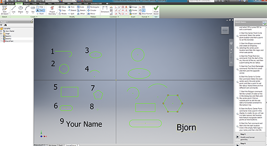
- image 1- 3D STARTING TO USE SCETCH fUNCTION
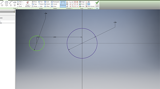
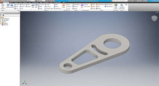
- image 2- MY FIRST PART
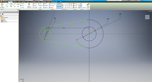
- image 3- MEASURING/RE-SIZING AND USING PARAMETERS
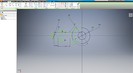
- image 4- MAKING SHURE EVERYTHING IS IN ORDER BEFORE EXTRUDING
- image 5- DONE
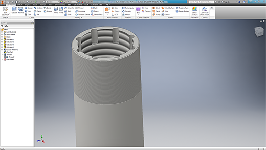
- image 6- lEARNING TO CUT HOLES/PATTRERNS OF FEATURES AND MAKING A THREAD
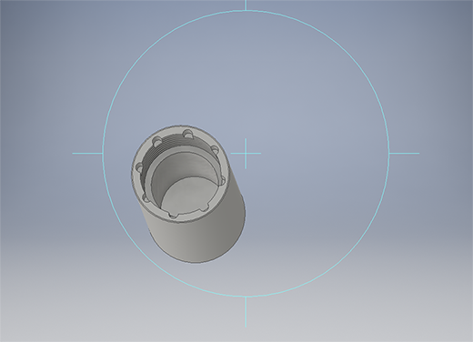
- image 7- DONE
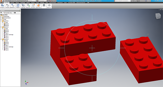
- image 8- BUILDING A LEGO BLOCK
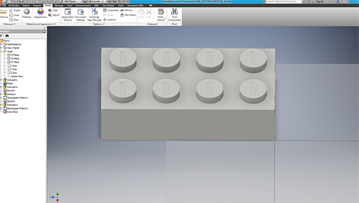
- image 9- CHANGING ITS MATERIAL, COLOR AND ASSEMBLING THEM
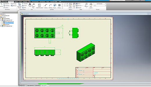
- image 10- LEGO TECHNICAL DRAWING
- image 11- BUILDING A HAT FOR MY GPS (my GPS over heats all the time due to the sun being so hot hence its time for a hat)
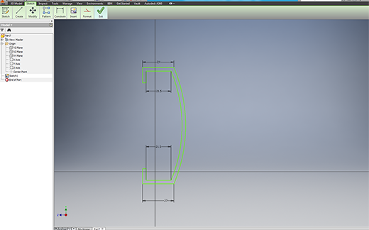
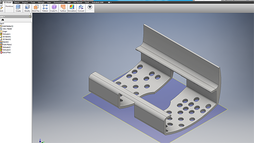
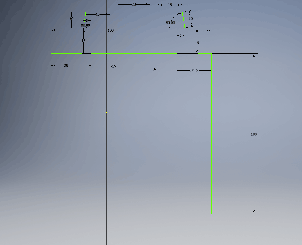
- image 12- EXTRUDING AND CUTTING
- image 13- ADDING A PATTERN OF HOLES
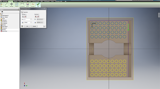
- image 14- HERE I MADE A PATTERN OF HOES AND PATTERND THE PATTERN
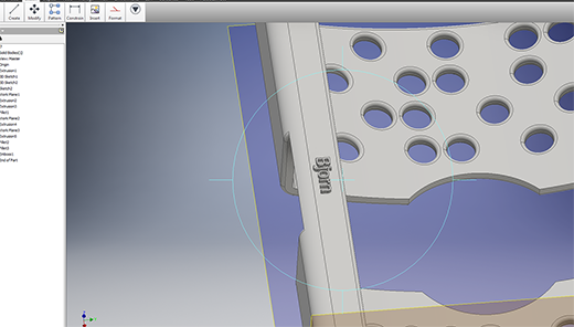
- image 15- ADDED MY NAME AS A LOGO (using etch function)
-
NOW FOR MY FINAL PROJECT
- As I am still building and thinking about my final projecT, I will start designing a simple table in CAD.
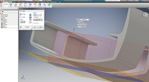
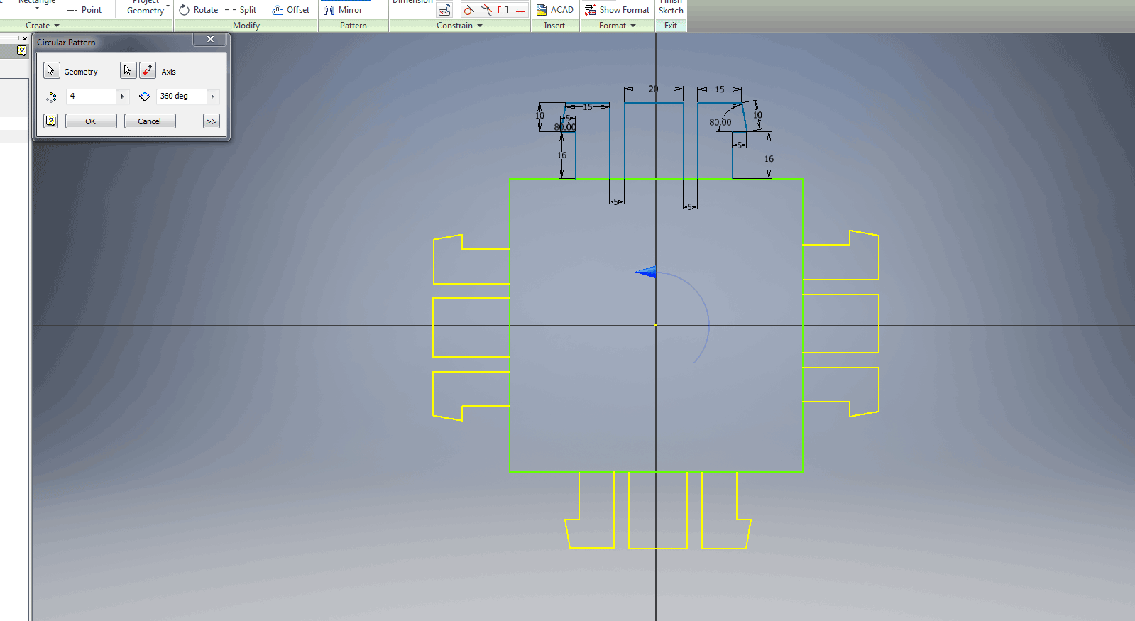
- STEP 1: Starting to design a snapfit joint that will be 3D Printed ABS and joint to 16mm wood
- I used the Circular Patern tool to duplicate mt snapfit pieces around the 100mm block and extruded it to 30mm thick (sorry no pic for this extrusion)
- As a second Part I started drawing the table, I reseached the dimensions for ergonomics and found that a sitting table hight is normally 900mm and a bar counter hight 1200mm, so I cose 1000mm as it is between a sitting table and bar counter which would eighter be to high or to low.
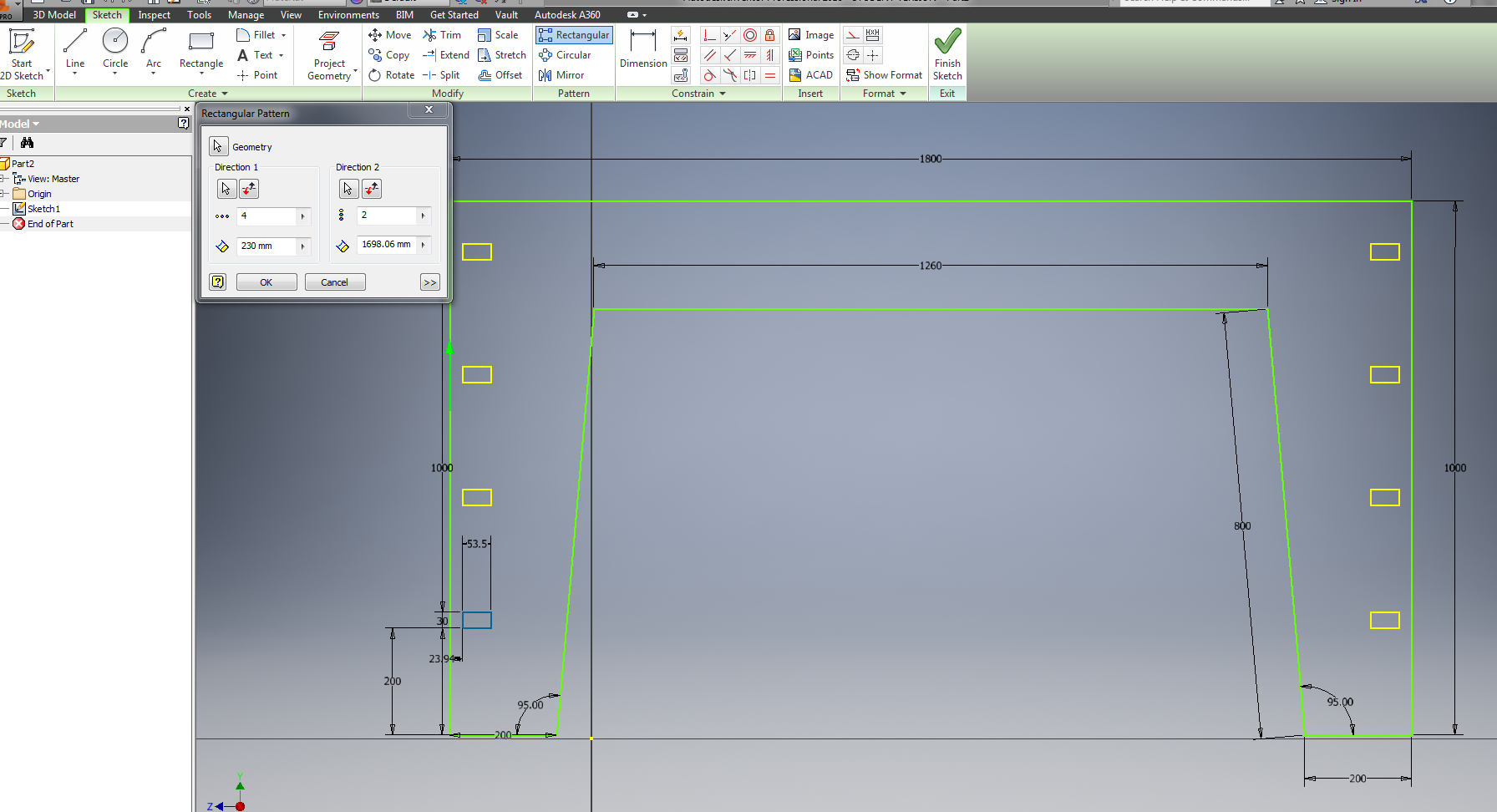
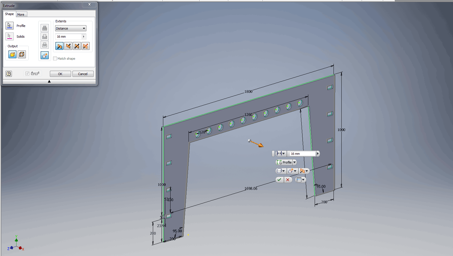
- Extruding to 16mm as the stock wood we have is 16mm.
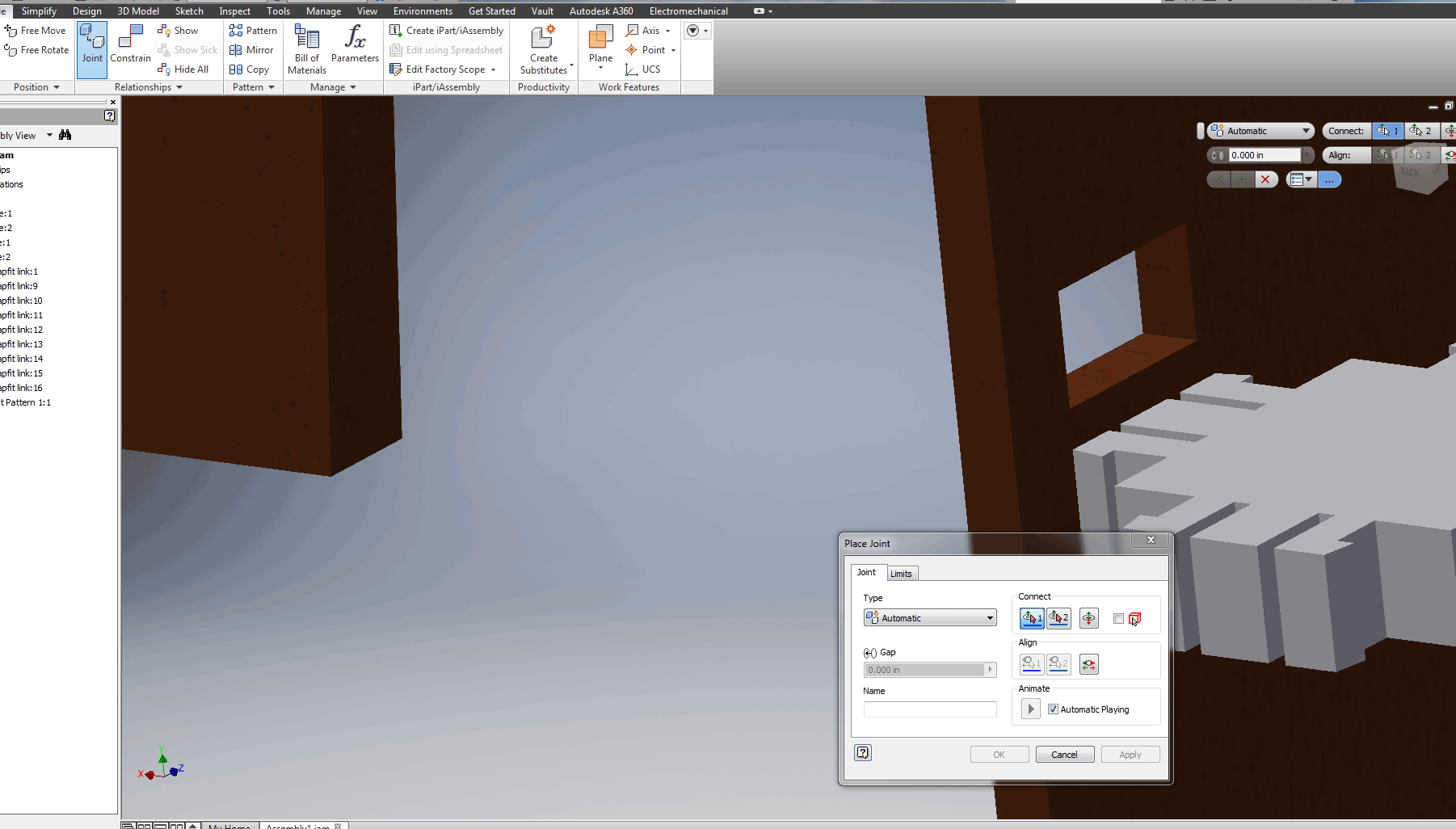
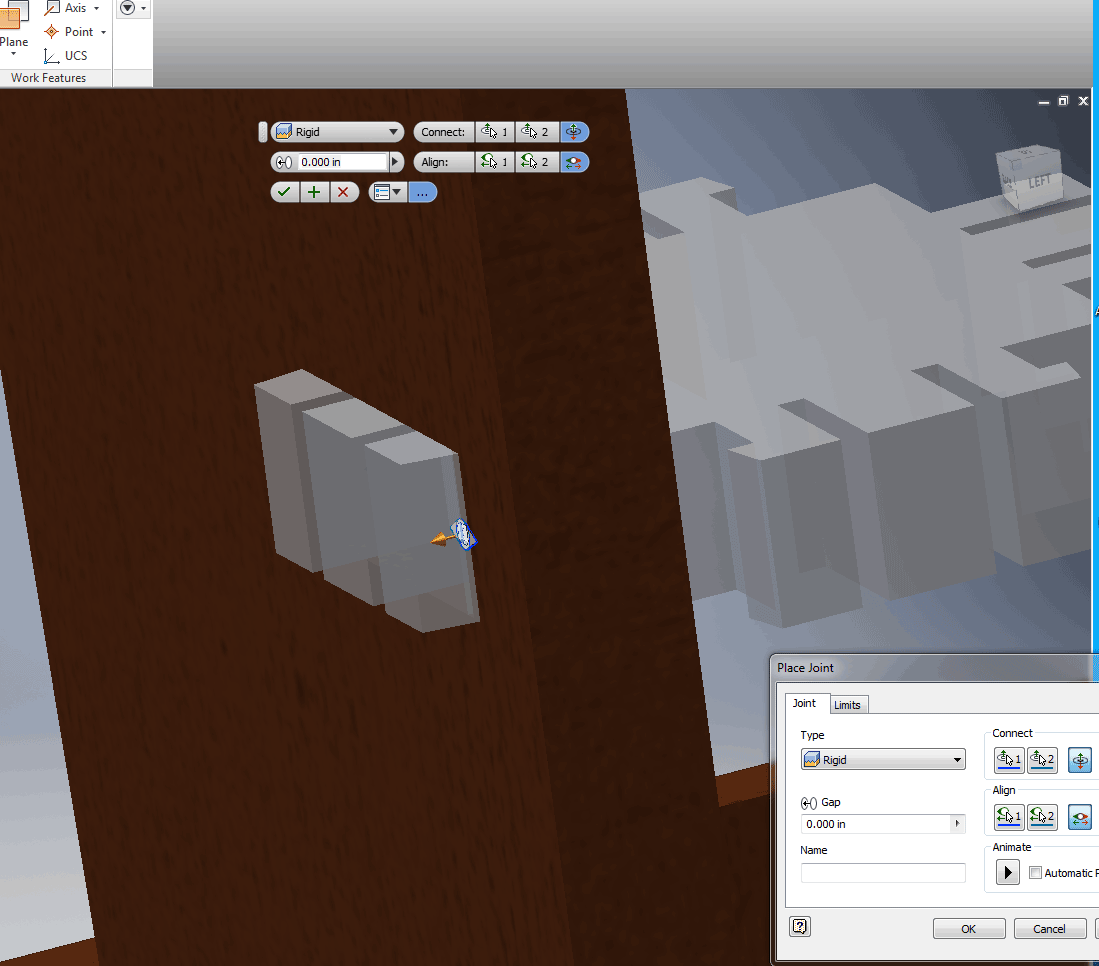
now for assembly
- Assembly in Inventor can be highly fustrating but after about 3 hours I figured it out. It is vitally important to choose the exact lines and points to make it work.
- Joint complete
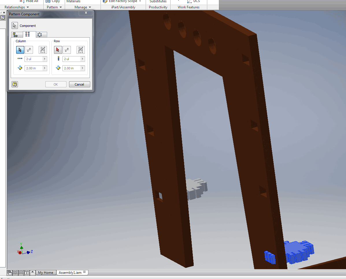
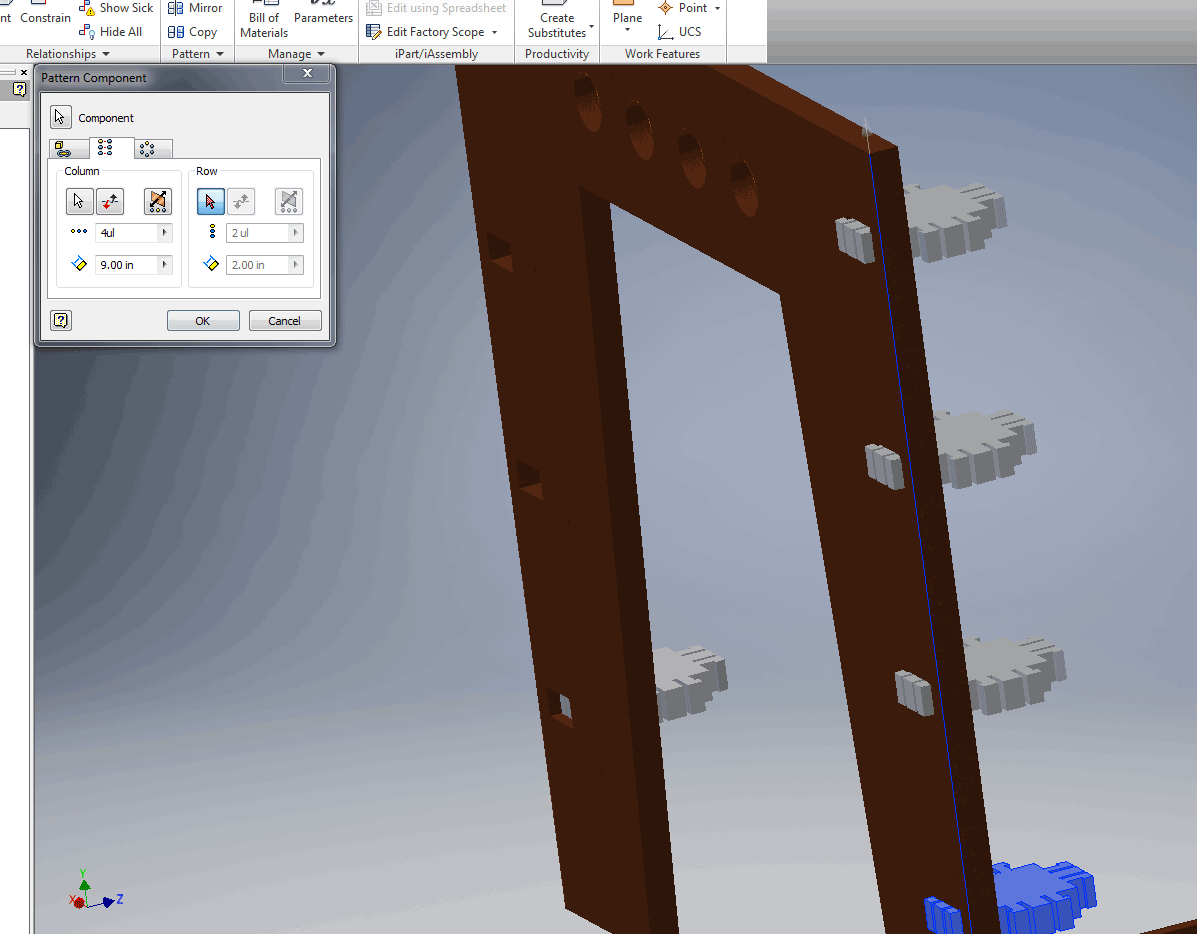
- I started to get highly fustrated because I had 16 more joints to do so I tried to make a pattern of the joint.
- This wordked perfectly
- Now joining the other part of the table
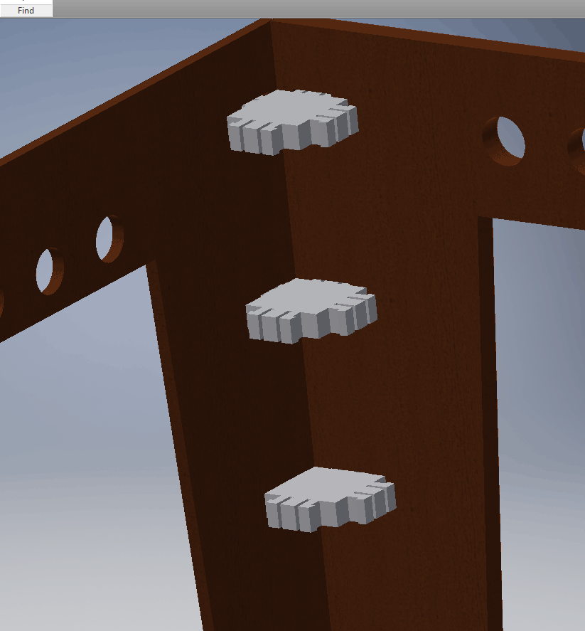
- Assembly complete (It is not the entire CAD drawing of my table as I dont know exactly what components etc I will need)
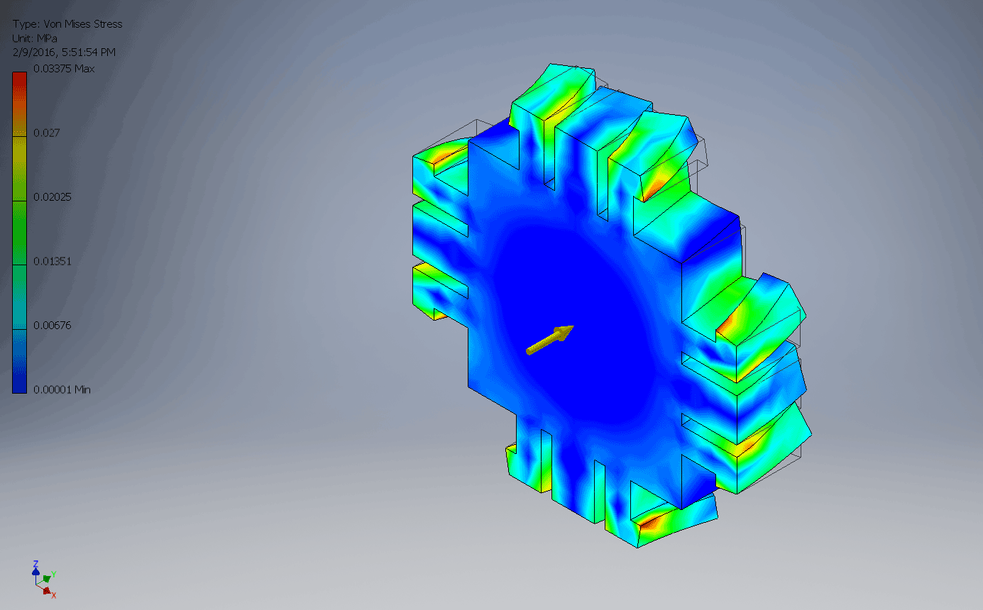
- Time for a stress test (Top bar, environments tab, Stress analyis)
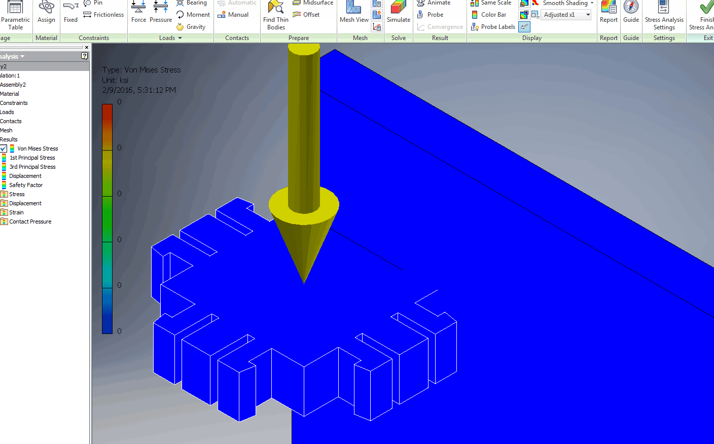
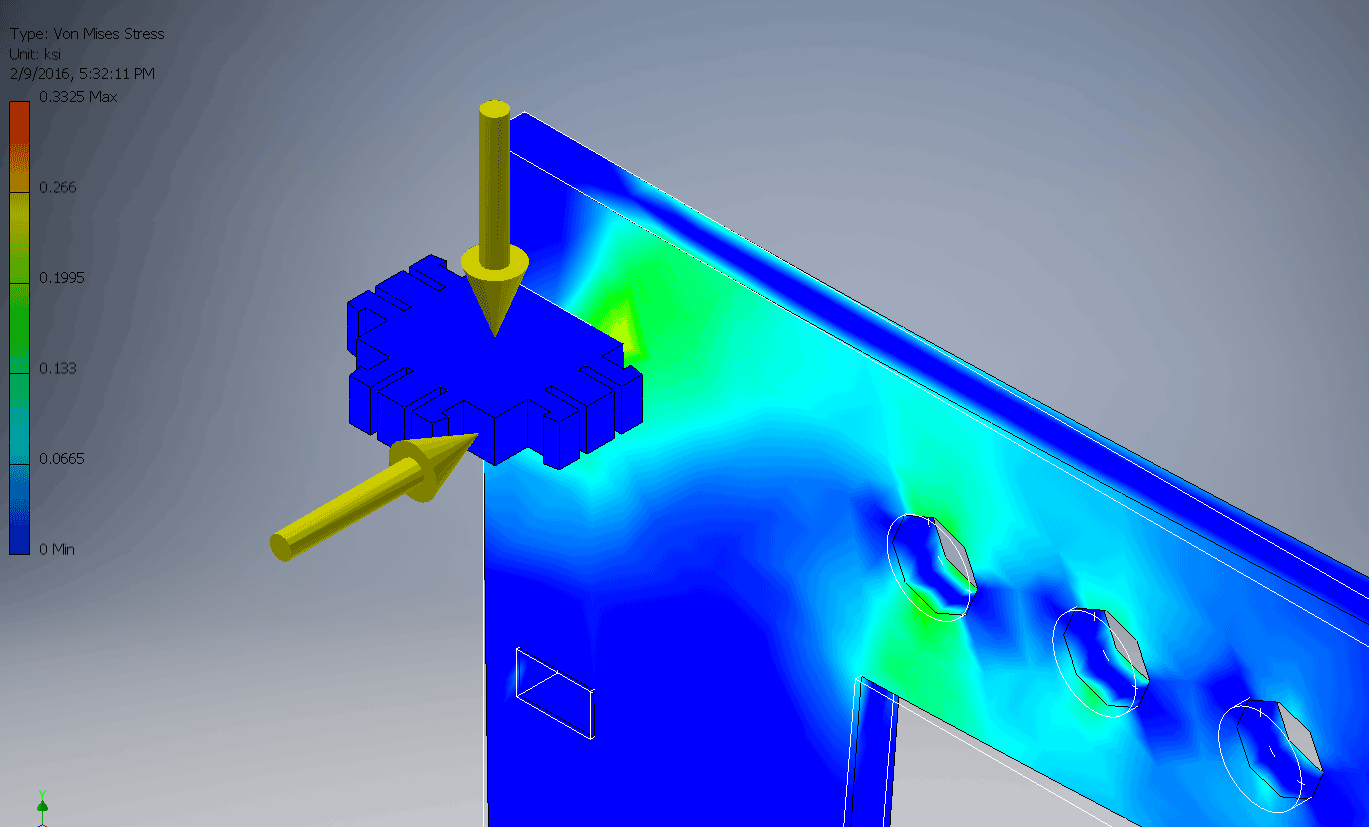
- So once I have created a simulation I had to first assign materials of each part, then constraints and finally add loads before selecting simulate.
- Rotated simulation
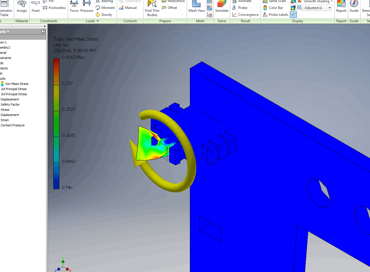 this simulation I did just for fun (it does get a liitle addicting) so its rotating at the back of the part with a pressure force in the front.
-
-
For my 2D Computer Aided Design lesson I decided to use Inkscape as suitable 2D software. I did look at Corel Draw and Adobe Photoshop both of which I know pretty well. Other versions of 2D software I looked at were GIMP and Inkscape which I ended off choosing because of user-friendliness.
For the 2D I decided to rather do a kind of a rough presentation drawing instead of a drawing that could be imported into 3D and converted into a technical drawing. - Doing the tutorials really helped to understand how the program works but also to know the different tools to use. It always helps me to know and understand what I want to achieve before starting with Computer Aided Design programs (for Inkscape tutorial please follow this link bellow) .
Attempting Inkscape
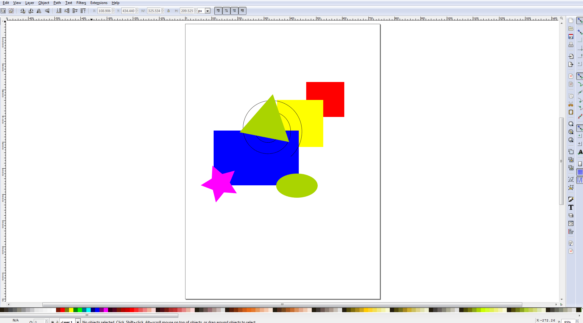
- Learning to create shapes,changing line qualities, color, fill and strocke.
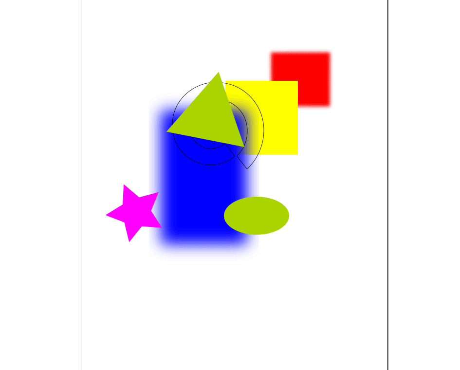
- Gradient Tool

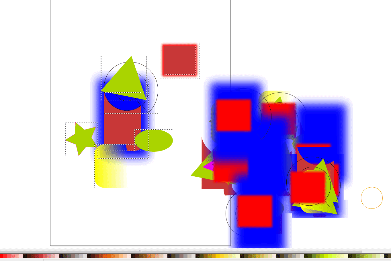
- Selecting numerous shapes and using spray can tool to duplicate them.
- Learning hoe to use line tools to cut, fill and change the properties of the shapes
now for my concept drawing
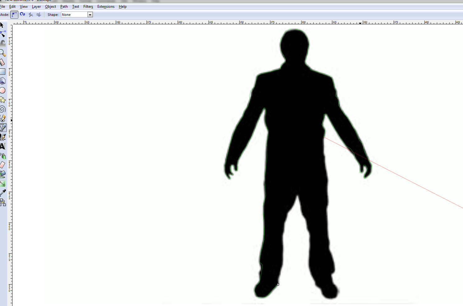
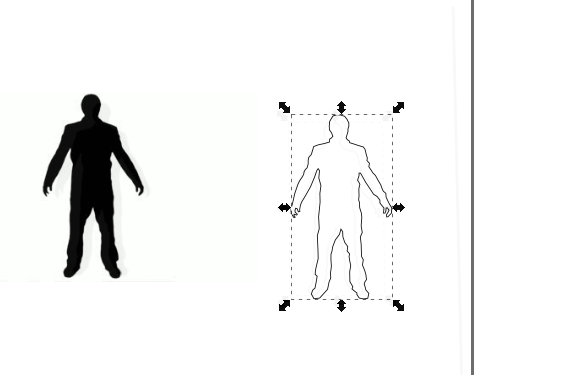
- I downloaded a man from the internet, imported hime and now tracing him with the Draw Bezier tool
- traced, now for adding a color and changing the opacity to make him see through
-
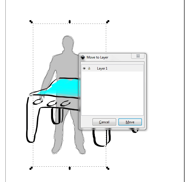
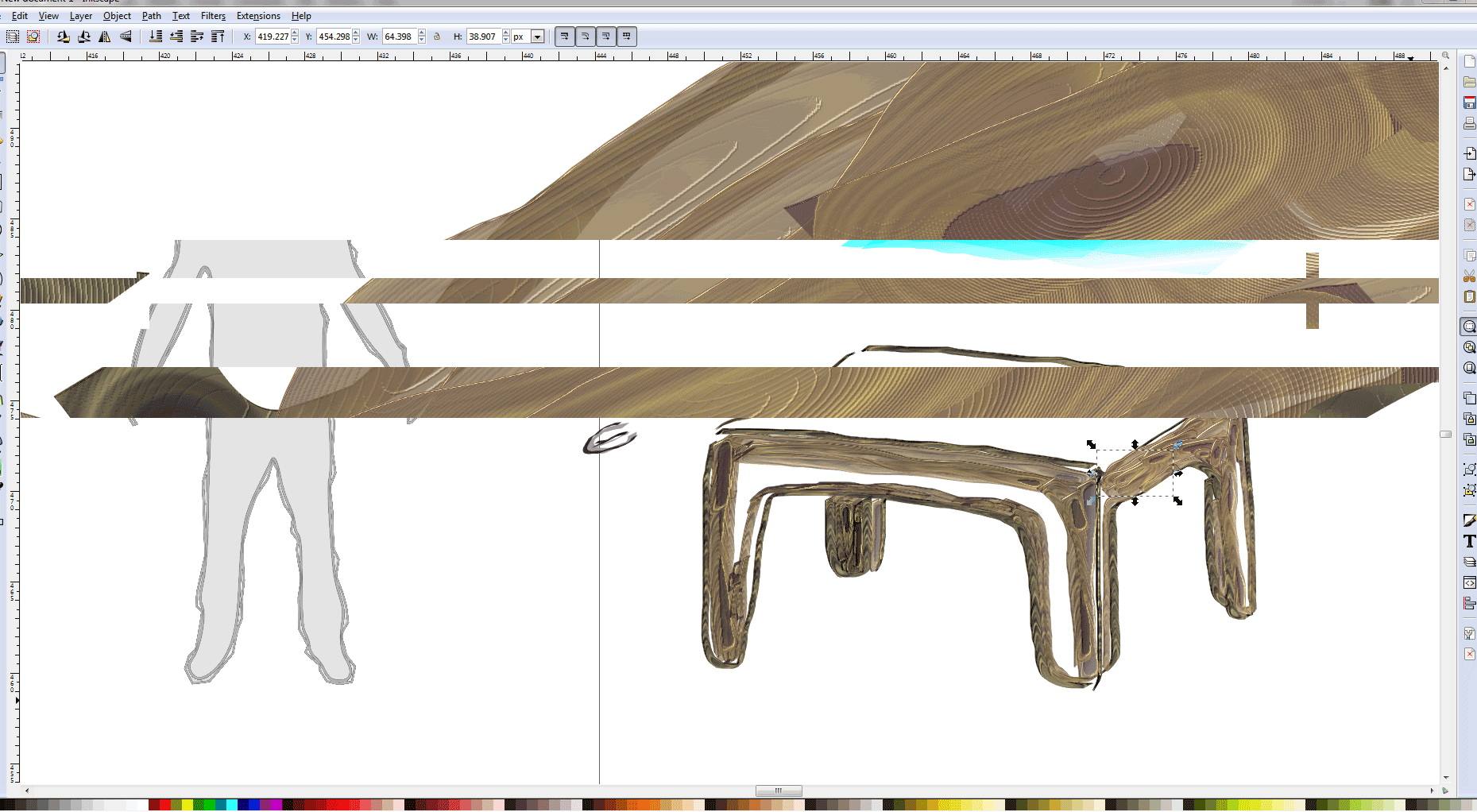
Here I am moving him to a layer so that he is in front of the Table. The table I drew with a Wacom tablet using the calligraphy tool.
- I started playing with the Filter library (be warned, your computer might crash)
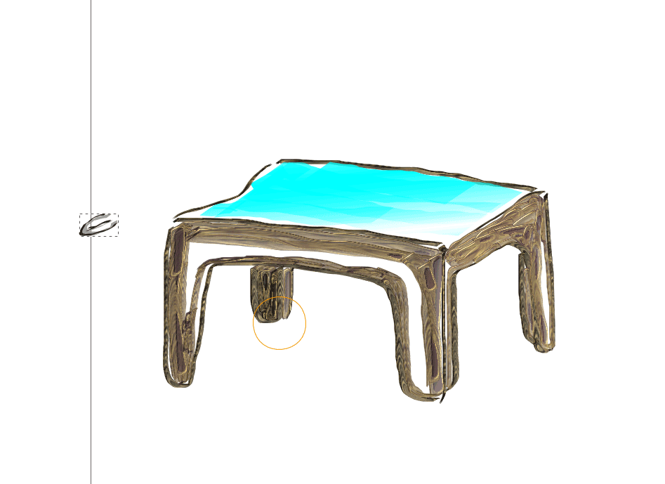
- using the spray can tool to add/ duplicate my handles)
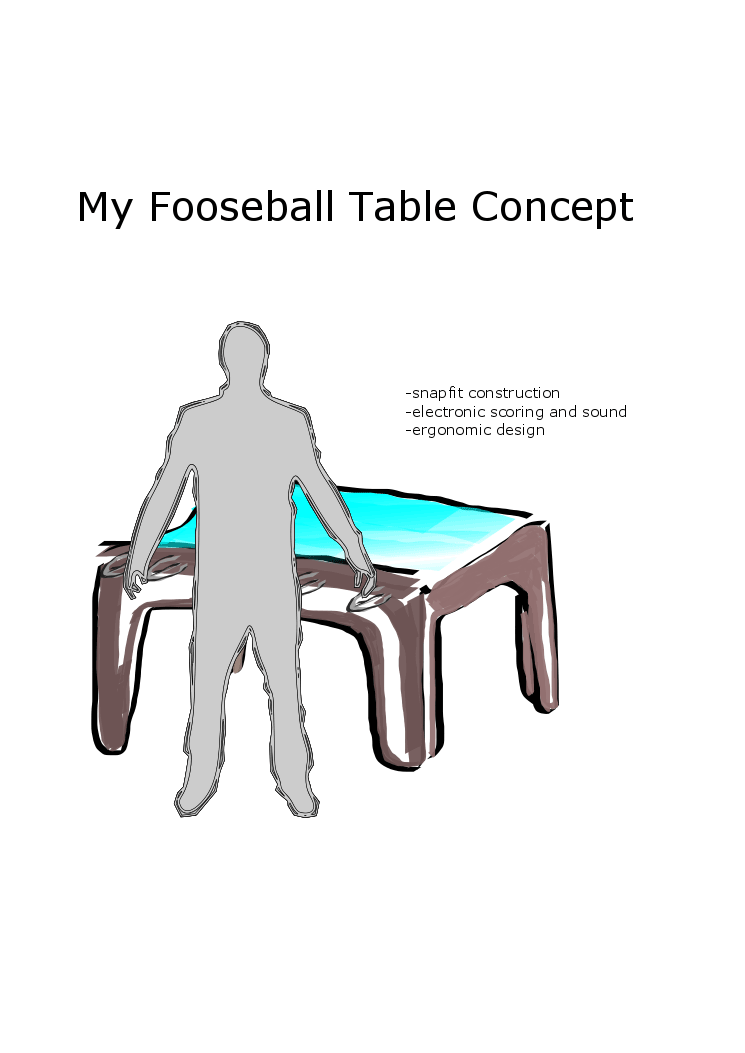
- Adding wording and saving
Issues I am still having with Inventor
- My Inventor tool bar in the above keeps changing which I find very strange.
- I am still exploring making exploded view videos and renderings.
- Making a exploded view and animation